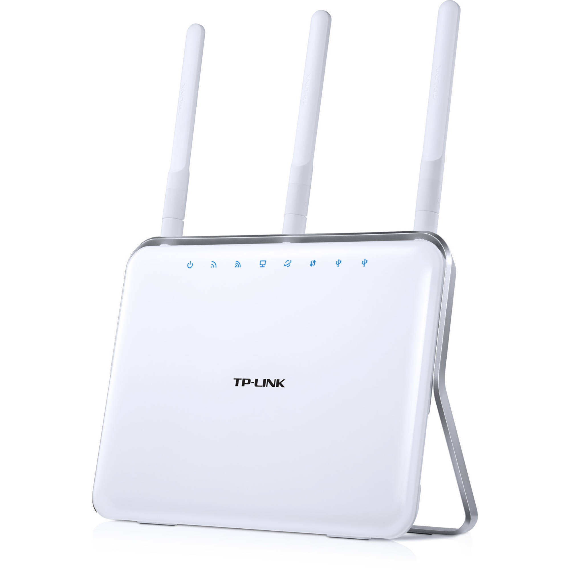
The TP-Link Archer C9 is one of the first consumer Wi-Fi routers that I got to tinker around with and learn more about networking. I loved the simple to configure web interface and the advanced settings that I could configure. I also liked its unique design (at the time) and use of external antennas. It was also a good value and performer with 80 MHz bandwidth capability on 5 GHz and very little downtime or issues. Unfortunately, it was superseded (we upgraded to) by Comcast’s XB-7 Gateway because we needed to subscribe to unlimited data and it was cheaper per month if we rented their gateway (that seems backward but it’s true).
One of the best things you can do to repurpose an old Wi-Fi router is to flash a custom firmware on it. These custom firmware can bring new life to older Wi-Fi routers by adding new features and more advanced configuration options. Some good choices are DDWRT and OpenWRT.
I wanted to flash a fork of OpenWRT called GoldenOrb. This version allows the use of cellular modems/modules and includes the necessary drivers and setup needed to use them. The problem is that after the initial release firmware of the router, TP-Link locked out the ability to flash any other firmware not signed by TP-Link, and locked out the ability to flash to an older version. There were ways to get around the downgrading of the firmware, however, TP-Link has patched those methods on subsequent versions.
Time to break out the soldering iron
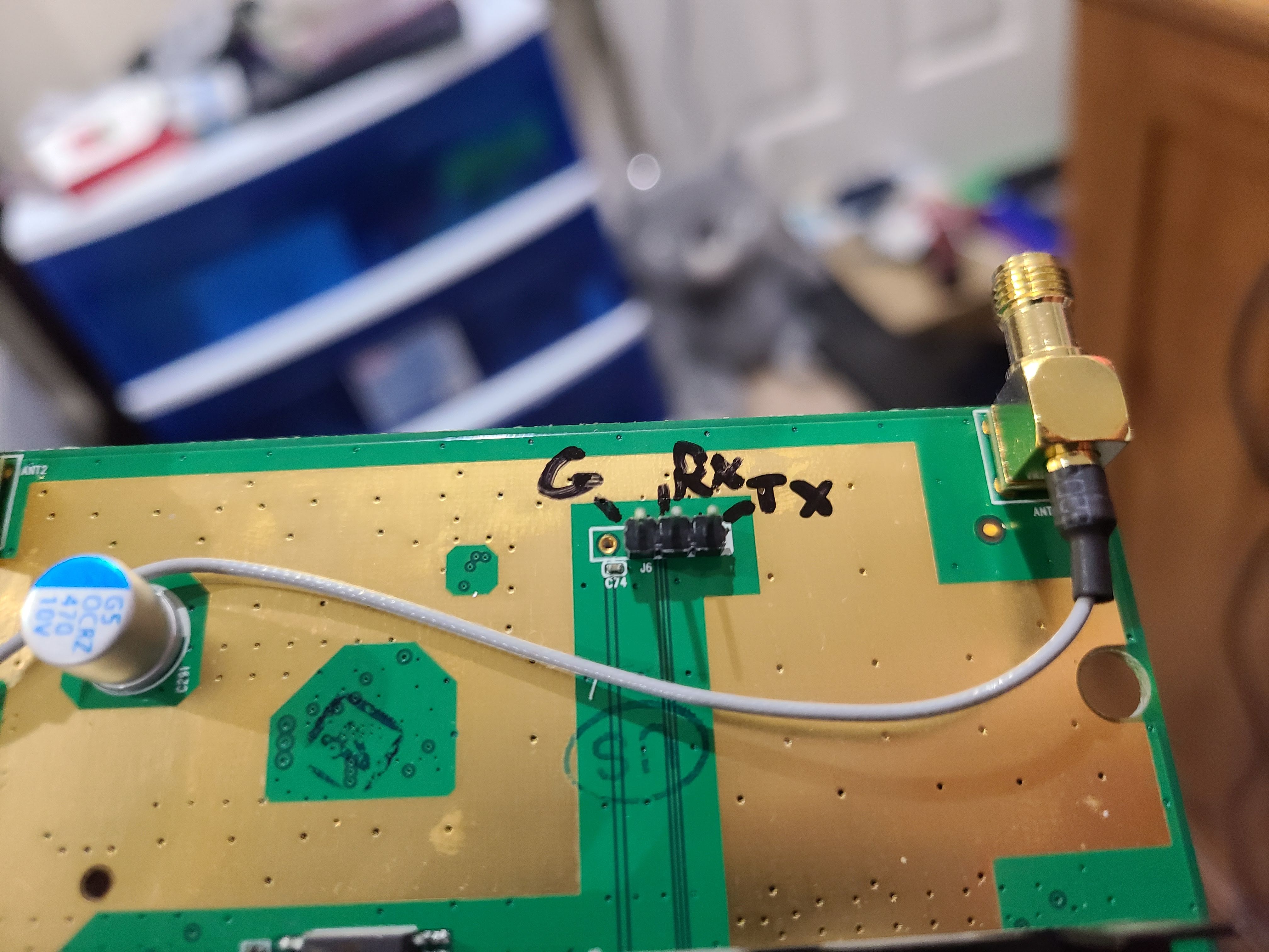
At this point, time was time to go nuclear. The previous methods like downgrading in recovery mode didn’t work. A lot of consumer electronics that have microcontrollers or microprocessors have some sort of diagnostic or debugging ports on them. These ports were used during the development of the product and in most cases are removed, disabled, or hidden in some way once it reaches mass production. In the router’s case, the ports were hidden and required soldering pin headers in the holes where they used to be on the board. These diagnostic pins communicated over serial (UART) and sent everything that was going on. It also allowed for sending commands. I followed this video as a guide. The trick is to reach the router’s bootloader before it boots into the Linux-based operating system. From there, we can send commands to flash any firmware without restriction.
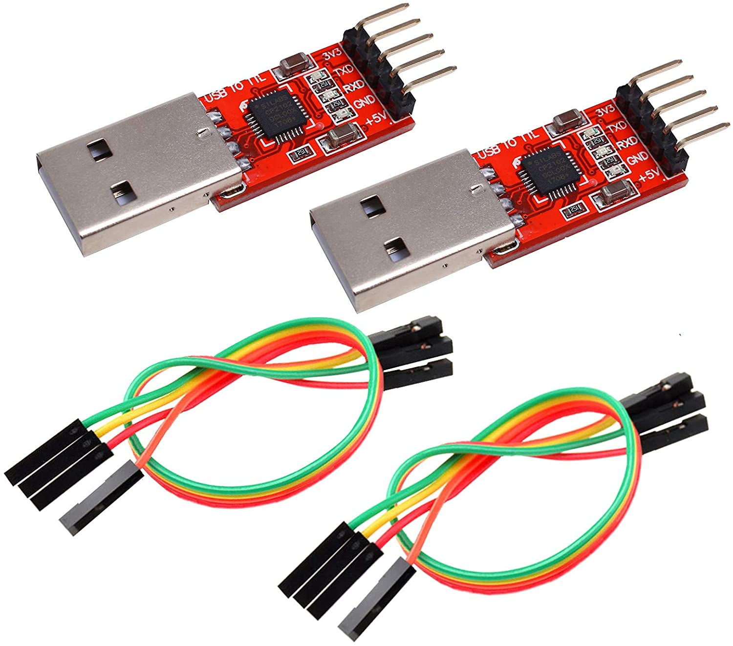
I had to purchase a UART adapter that would send the data over USB to my computer. I purchased on Amazon an adapter and it was recommended to get one that has the CP2102 chipset from Silicon Labs.
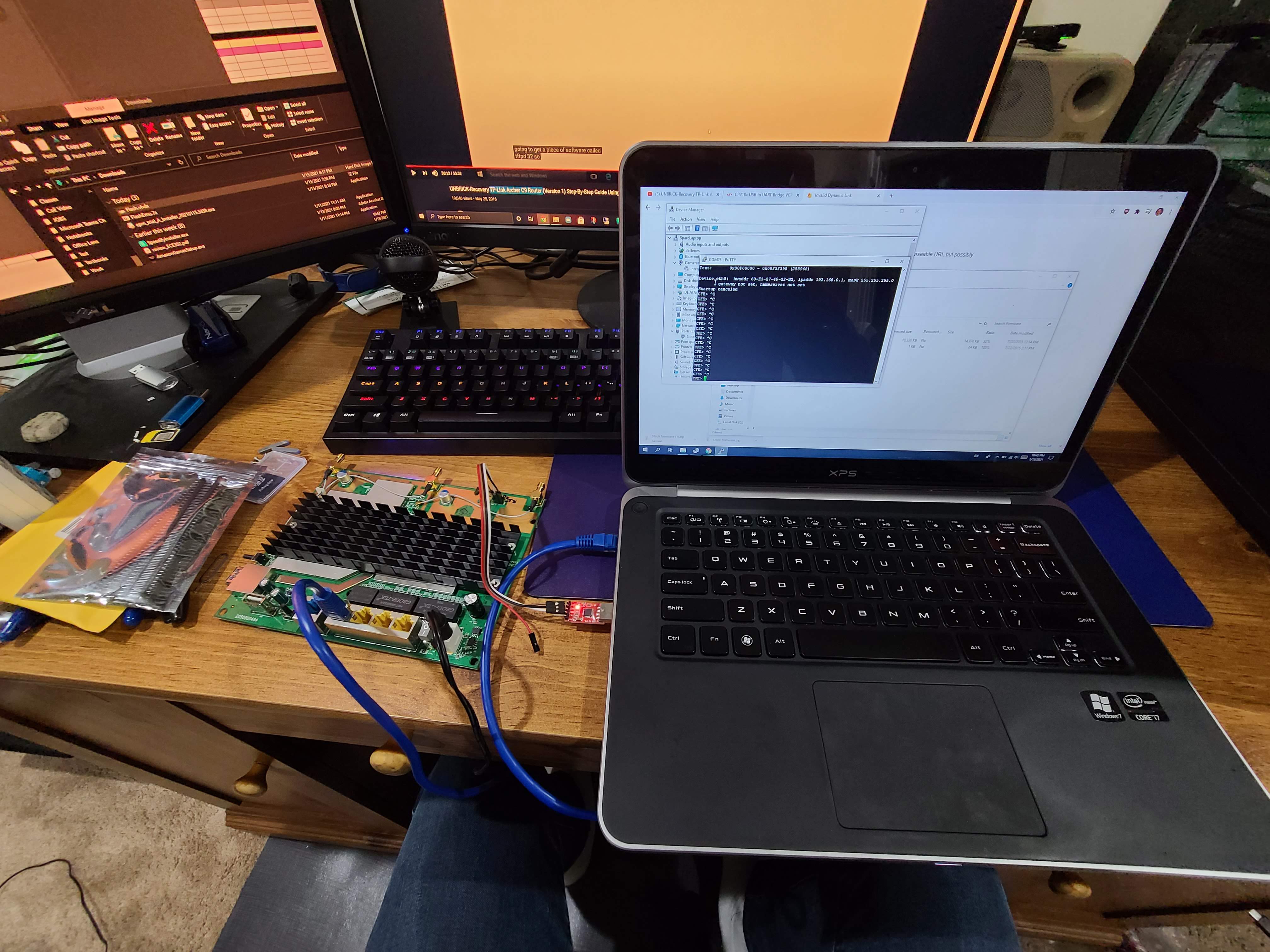
The firmware is sent over ethernet (UART would be too slow) as it creates a TFTP server for file transfer. UART uses three pins, receive (RX), transmit (TX), and ground (G). I highly recommend labeling what each one is as they are not indicated on the board. I used a program called PuTTY. It is my go-to for SSH and serial communications.
Conclusion
The hardest parts of this project were:
- Opening the router. There were many plastic tabs and pins and I probably broke a few on the way in.
- Solding the pin headders. Having the proper eqipment helps, but it took some time debugging why I couldn’t get the serial communcation going. I traced it down to poor solder connections.
- Reaching the bootloader. The serial output goes by fast and you have to watch at a certian point when to press Ctrl+C to stop the boot process and reach the bootloader shell
But the reward at the end of essentially taking ownership of the router and being able to do whatever I want with it is awesome! I felt that I was sticking it to TP-Link (not that I have anything against them). This project was very valuable in learning how single-board computers work from the bootloader to serial communications.